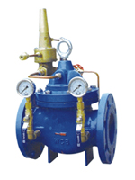
一、 Structure and purpose
A valve used between water supply/back of an air conditioning system order to balance the pressure differential and able to raise the system’s utility.keep the pressure differential at an accurately constant value and to lower ths system’s noise and the damage to the equipment due to an extra-big pressure differential to the utmost extent.1t is superior to the other balancing valves,needs no other execution machinery,gets the system balanced completely depend-ing on the pressure differential of the medium’s own and saves energy and the installation space.
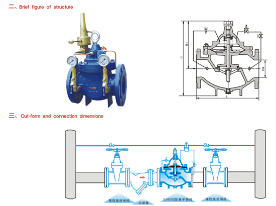
四、 Schematic diagram of installation
| 公称通径 DN(mm) |
20 |
25 |
32 |
40 |
50 |
65 |
80 |
100 |
125 |
150 |
200 |
250 |
300 |
350 |
400 |
450 |
500 |
| L |
180 |
180 |
180 |
203 |
203 |
216 |
241 |
292 |
330 |
356 |
495 |
622 |
698 |
787 |
914 |
978 |
978 |
| PN10 |
D |
105 |
115 |
135 |
145 |
160 |
180 |
195 |
215 |
245 |
280 |
335 |
390 |
440 |
500 |
565 |
615 |
670 |
| D1 |
75 |
85 |
100 |
110 |
125 |
145 |
160 |
180 |
210 |
240 |
295 |
350 |
400 |
460 |
515 |
565 |
620 |
| PN16 |
D |
105 |
115 |
135 |
145 |
160 |
180 |
195 |
215 |
245 |
280 |
335 |
405 |
460 |
520 |
580 |
640 |
705 |
| D1 |
75 |
85 |
100 |
110 |
125 |
145 |
160 |
180 |
210 |
240 |
295 |
355 |
410 |
470 |
525 |
585 |
650 |
| PN25 |
D |
105 |
110 |
135 |
145 |
160 |
180 |
195 |
230 |
270 |
300 |
360 |
425 |
485 |
550 |
610 |
660 |
730 |
| D1 |
75 |
85 |
100 |
110 |
125 |
145 |
160 |
190 |
220 |
250 |
310 |
370 |
430 |
490 |
550 |
600 |
660 |
| H |
550 |
560 |
575 |
590 |
610 |
625 |
642 |
750 |
808 |
864 |
1135 |
1185 |
1325 |
1385 |
1445 |
1545 |
1720 |
| H1 |
125 |
130 |
135 |
145 |
160 |
180 |
200 |
270 |
310 |
320 |
370 |
430 |
480 |
525 |
580 |
635 |
705 |
Note:Either elastic seat ring sealed gate valve or butterfly valve can be selected in the schematic diagram of installation.Recommended to select the butterfly valve in case of≥DN350
|