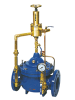
一、Structure and purpose
Use in a pipeline system to prevent it from surpassing pressure or keep the pressure of it.to reduce the water hammer’s shock after the pump is closed and also and also used as a water hammer remover for a large water supply system.On the inlet of the valve’s control system a self cleaning filter screen is placed,which,by means of the bigger specific gravity of the fluid,stops the suspension grains of a bigger specific gravity and diameter going into the sys-tern to ensure the main valve’s water supply pressure at the upstream at a set value to get the system smoothly circulated without any resistance.This valve features sensitive open-close,safety,reliability,stable motion and long duration
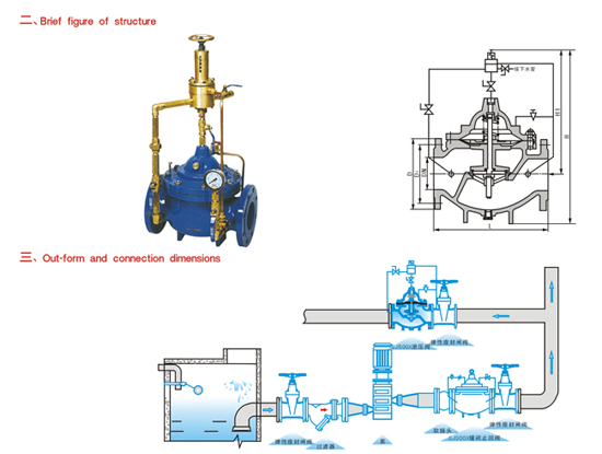
四、Schematic diagram of installation
| 公称通径 DN(mm) |
20 |
25 |
32 |
40 |
50 |
65 |
80 |
100 |
125 |
150 |
200 |
250 |
300 |
350 |
400 |
450 |
500 |
| L |
180 |
180 |
180 |
203 |
203 |
216 |
241 |
292 |
330 |
356 |
495 |
622 |
698 |
787 |
914 |
978 |
978 |
| PN1O |
D |
105 |
115 |
135 |
145 |
160 |
180 |
195 |
215 |
245 |
280 |
335 |
390 |
440 |
500 |
565 |
615 |
670 |
| D1 |
75 |
85 |
100 |
110 |
125 |
145 |
160 |
180 |
210 |
240 |
295 |
350 |
400 |
460 |
515 |
565 |
620 |
| PN6 |
D |
105 |
115 |
135 |
145 |
160 |
180 |
195 |
215 |
245 |
280 |
335 |
405 |
460 |
520 |
580 |
640 |
705 |
| D1 |
75 |
85 |
100 |
110 |
125 |
145 |
160 |
180 |
210 |
240 |
295 |
355 |
410 |
470 |
525 |
585 |
650 |
| PN25 |
D |
105 |
110 |
135 |
145 |
160 |
180 |
195 |
230 |
270 |
300 |
360 |
425 |
485 |
550 |
610 |
660 |
730 |
| D1 |
75 |
85 |
100 |
110 |
125 |
145 |
160 |
190 |
220 |
250 |
310 |
370 |
430 |
490 |
550 |
600 |
660 |
| H |
550 |
550 |
550 |
610 |
610 |
625 |
645 |
750 |
808 |
864 |
1135 |
1185 |
1325 |
1385 |
1445 |
1325 |
1430 |
| H1 |
460 |
460 |
460 |
516 |
516 |
520 |
538 |
596 |
655 |
710 |
805 |
855 |
955 |
990 |
1030 |
905 |
960 |
Note:Either elastic seat ring sealed gate valve or butterfly valve can be selected in the schematic diagram of installation.Recommended to select the butterfly valve in case of≥DN350
|