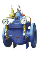
一、Structure and purpose
This valve utilizes the self energy of a medium to adjust the pipeline pressure and controls the outlet pressure of the main valve via the adjustment of the pressure reducing pilot valve. The outlet pressure does not change along with the variation of the inlet one and of the water quantity at the outlet. Reli-able sealing performance, easy installation, maintenance, debugging and check, long duration.
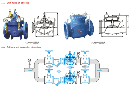
四、 schematic diagram of installation
| 公称通径 DN(mm) |
20 |
25 |
32 |
40 |
50 |
65 |
80 |
100 |
125 |
150 |
200 |
250 |
300 |
350 |
400 |
450 |
500 |
600 |
700 |
800 |
| L |
180 |
180 |
180 |
203 |
203 |
216 |
241 |
292 |
330 |
356 |
495 |
622 |
698 |
787 |
914 |
978 |
978 |
1295 |
1446 |
1956 |
| PN10 |
D |
105 |
115 |
135 |
145 |
160 |
180 |
195 |
215 |
245 |
280 |
335 |
390 |
440 |
500 |
565 |
615 |
670 |
780 |
895 |
1010 |
| D1 |
75 |
85 |
100 |
110 |
125 |
145 |
160 |
180 |
210 |
240 |
295 |
350 |
400 |
460 |
515 |
565 |
620 |
725 |
840 |
950 |
| PN16 |
D |
105 |
115 |
135 |
145 |
160 |
180 |
195 |
215 |
245 |
280 |
335 |
405 |
460 |
520 |
580 |
640 |
705 |
840 |
910 |
1020 |
| D1 |
75 |
85 |
100 |
110 |
125 |
145 |
160 |
180 |
210 |
240 |
295 |
355 |
410 |
470 |
525 |
585 |
650 |
770 |
840 |
950 |
| PN25 |
D |
105 |
110 |
135 |
145 |
160 |
180 |
195 |
230 |
270 |
300 |
360 |
425 |
485 |
550 |
610 |
660 |
730 |
840 |
955 |
1070 |
| D1 |
75 |
85 |
100 |
110 |
125 |
145 |
160 |
190 |
220 |
250 |
310 |
370 |
430 |
490 |
550 |
600 |
660 |
770 |
875 |
990 |
| H |
342 |
342 |
342 |
395 |
395 |
405 |
430 |
510 |
560 |
585 |
675 |
730 |
760 |
840 |
910 |
1030 |
1135 |
1270 |
1460 |
1640 |
| H1 |
247 |
247 |
247 |
278 |
278 |
298 |
313 |
350 |
365 |
420 |
450 |
470 |
490 |
526 |
570 |
610 |
665 |
725 |
865 |
975 |
Note:Either elastic seat ring sealed gate valve Or butterfly valve can be selected in the schematic diagram of installation.to select the butterfly valve in case of ≥DN350.
|