 |
| 一、产品概述Brief introduction of product |
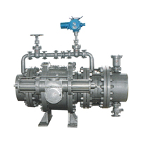
水电站型液控缓闭球阀是对液控缓闭蝶阀应用范围的有力补充,特别适用于高水头的水电站工况。工作时,阀门与水轮机配合,按照水力
过渡过程原理,通过预设的启闭程序,有效消除管路水锤,实现管路可靠截止,起到保护管路系统安全的作用。
本系列液控缓闭球阀,智能化程度高、功能齐全、性能稳定可靠,且流阻系数极小,全开时的流阻系数与管道相等。我公司并可根据用户
的特殊要求单独进行设计,多方位满足用户对该类产品的需要。
1、流体阻力小,球阀是所有阀类中流体阻力最小的一种,即使是缩径球阀,其流体阻力也相当小。
2、开关迅速、方便,只要阀杆转动900,球阀就完成了全开或全关动作,很容易实现快速启闭。
3、密封性能好。球阀阀座密封圈一般采用聚四氟乙烯等弹性材料制造,易于保证密封,而且球阀的密封力随着介质压力的增加而增大。
4、阀杆密封可靠。球阀启闭时阀杆只做旋转运动,因此阀杆的填料密封不易被破坏。
5、球阀的启闭只做90。转动,故易实现自动化控制和远距离控制,球阀可配置气动装置、电动装置、液动装置、气液联动装置或电液联动
装置。
Power plant hydraulic control slow closing ball valve is a valuable complementarity for the hydraulic control slow closing butterfly valve. It specially fits for high head
water power plant. It coordinates with hydroturbine, working as per the hydraulic transition principle, effectively eliminates the water hammer effect and ensures reliable shut-
off of pipeline by preset program, therefore, protects the safety of pipelines. This series of hydraulic control slow closing ball valve is with high degree of intelligence, complete
functions, reliable performance and low flow resistance coefficient, the flow resistance coefficient at full opening is similar with the pipeline.We also provide tailor-made
solutions according to user’s unique requirement and meet the users needs in every aspects.
1 . Low flow resistance. ball valve is with the lowest flow resistance among the valves, even if the reduced port ball valve, the flow resistance is still very low.
2. Swift and convenient opening and closing. By turning 900 , the ball valve completes full opening or full closing action, which makes it ideal for fast opening and closing.
3. Excellent sealing. The seat ring of ball valve is mainly resilient material like PTFE, which ensures perfect sealing, furhtermore, the sealing strength of ball valve increases simultaneously with the medium pressure.
5. The ball valve achieves opening and closing by rotating 900 , which makes it easy to realize automatic control and remote control. Ball valve can be equipped with pneumatic actuator, electric actuator, hydraulic actuator, gas over oil actuator or electric hydraulic actuator. |
| 二、设计与制造标准Design and manufacturer standard |
设计与制造Design and manufacturing: GB/T14478 GB/T12237
法兰标准Flange Standard:GB/T9112-9124 GB12380.1-12380.3
蓄能器标准Standard of Energy storage vessel: GB/T2352 |
传动装置Actuation: JB/T5299
结构长度Face to face length:GB/T12221
试验与检验Inspection and test: GB/T14478 GB/T13927 |
| 三、基本参数Basic Parameters |
油泵电源
Oil Pump electricity supply |
AC380V/50Hz |
控制电源
Control power supply |
DC220V |
泵站设计压力
Design pressure of pump station |
31.5MPa
|
泵站工作压力
Working pressure of pump station |
13-16MPa |
系统压力设定
System Pressure Setting
|
上限
Upper Limit
|
16MPa
|
油缸工作压力
Working pressure of oil cylinder
|
13-16MPa |
下限
Lower limit |
13MPa
|
泵站用液压油
Hydraulic olfor pump staion |
N46-N68号 |
通径范围DN (mm)
Nominal diameter |
300-1600
|
公称通径
Nominal diameter |
<700
|
≥700 |
压力范围PN( Mpa)
NOminal Pressure |
2.5-10
|
开阀时间(90度)
Opening time |
10-60S(可调)
10-60S(Adjustable) |
30-90S(可调)
|
试验压力
Ps(Mpa) Testing Pressure
|
密封Seat
|
1.1×PN
|
关阀时间(90度)
Closing time (90 Degrees)
|
快关
Fast closing
|
3-20S
|
6-30S
|
强度Shell |
1.5×PN |
慢关
Slow closing |
6-60S
|
10-90S
|
工作压力(MDa)
Workina Pressure
|
≤1.0×PN
|
关阀角度 |
快关
Fast closing
|
70±10度
|
70±10度
|
介质温度(℃)
Medium temperature |
≤80 |
|
慢关
Slow closing |
20±10度
|
20±10度
|
适用介质
Applicable Medium |
清水、海水、泥沙水、油品等
Water, Sea water, Slurry, Oil etc |
防护等级
Protection Level |
lp56 | |
| 四、主要零件选用材料Mian prts and materia |
| 零件名称Part Name |
材料Material |
| 阀体body |
球墨铸铁、碳素钢Ductile lron,Carbon steel |
| 球体Ball |
球墨铸铁、碳素钢Ductile iron,Carbon steel |
| 阀轴Shaft |
不锈钢、碳素钢Stainless Steel,Carbon Steel |
| 阀座Seat |
PTFE; PPL |
| 球体密封体Ball seat |
不锈钢Stainless Steel |
| 滑动轴承Bushing |
CSB自润滑轴承CSB Self-Iubricated bearing |
| 填料Packing |
V形密封圈、柔性石墨V-shape sealing ring,Flexible graphite |
| 传动箱体Transmission box |
WCB |
|
|
| ―、产品概述Br ief introduct ion of product |
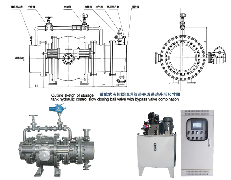
双作用式液控缓闭球阀是对液控缓闭球阀、球阀应用范围的有力补充,特别适用于高水头的水电站工况。工作时,阀门与水轮机配合,按照水力过渡过程原理,通过预设的启闭程序,有效消除管路水锤,实现管路可靠截止,起到保护管路系统安全的作用。本系列双作用式液控缓闭球阀,具有重锤蓄能、蓄能器蓄能双重蓄能方式,智能化程度高、功能齐全、性能稳定可靠,且流阻系数极小,全开时的流阻系数与管道相等。我公司并可根据用户的特殊要求单独进行设计,多方位满足用户对该类产品的需要。
Double acting hydraulic control slow closing ball valve is a valuable addition for the hydraulic control slow closing ball valve and butterfly valve. It specially fits for high head water power plant. It coordinates with hydroturbine, working as per the hydraulic transition principle, effectively eliminates the water hammer effect and ensures reliable shut-oft of pipeline by preset program, therefore, protects the safety of pipelines. This series of double acting hydraulic control slow closing ball valve is energized by dual energy storage, namely, counter weight and storage tank, with high degree of intelligence, complete functions, reliable performance and low flow resistance coefficient, the flow resistance coefficient at full opening is similar with the pipeline. We also provide tailor-made solutions according to user’s unique requirement and meet the user s needs in every aspects.
|
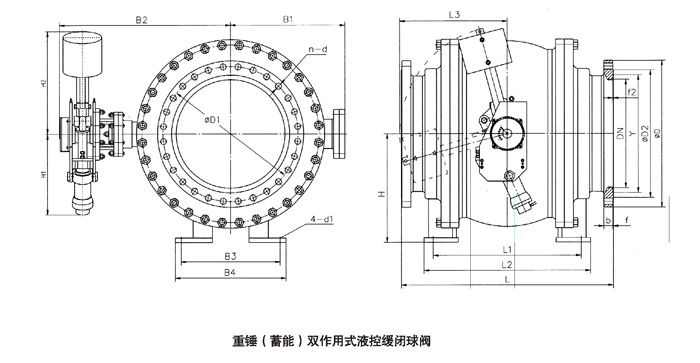 |
| S水电站型重锤(蓄能)双作用式液控缓闭球阀主要外形尺寸(PN=4. OMpa) 单位: (mm) |
公称通径
DN |
L |
D |
D1 |
Y |
b |
f2
|
n
|
d
|
L1
|
L2
|
H
|
H1
|
H2
|
B1
|
B2
|
B3
|
B4
|
d1
|
| 300 |
390 |
515 |
450 |
364 |
42 |
3 |
16 |
33 |
1000 |
250 |
350 |
495 |
965 |
280 |
838 |
320 |
380 |
32 |
| 350 |
430 |
580 |
510 |
422 |
46 |
4 |
16 |
36 |
1400 |
300 |
390 |
840 |
1380 |
305 |
860 |
320 |
380 |
32 |
| 400 |
530 |
660 |
585 |
474 |
50 |
4 |
16 |
39 |
1400 |
350 |
430 |
840 |
1380 |
365 |
930 |
340 |
420 |
32 |
| 500 |
630 |
755 |
670 |
576 |
55 |
4 |
20 |
42 |
1400 |
400 |
480 |
840 |
1380 |
440 |
1050 |
400 |
500 |
32 |
| 600 |
800 |
890 |
795 |
676 |
60 |
4 |
20 |
48 |
1600 |
450 |
550 |
915 |
1575 |
525 |
1105 |
450 |
550 |
35 |
| 700 |
900 |
995 |
900 |
778 |
64 |
4 |
24 |
48 |
1800 |
500 |
600 |
1030 |
1755 |
555 |
1300 |
570 |
700 |
35 |
| 800 |
1000 |
1140 |
1030 |
883 |
72 |
4 |
24 |
56 |
1800 |
550 |
670 |
1030 |
1755 |
605 |
1350 |
650 |
780 |
42 |
| 900 |
1100 |
1250 |
1140 |
988 |
76 |
4 |
28 |
56 |
2100 |
600 |
730 |
1120 |
2050 |
670 |
1410 |
700 |
860 |
42 |
| 1000 |
1200 |
1360 |
1250 |
10914 |
80 |
5 |
28 |
56 |
2100 |
650 |
780 |
1120 |
2050 |
755 |
1530 |
740 |
900 |
42 |
| 1100 |
1250 |
1460 |
1350 |
1194 |
84 |
5 |
28 |
56 |
2100 |
700 |
830 |
1120 |
2050 |
755 |
1580 |
760 |
920 |
42 |
| 1200 |
1300 |
1575 |
1460 |
1294 |
88 |
5 |
32 |
62 |
2300 |
750 |
890 |
1255 |
2230 |
855 |
17010 |
790 |
950 |
42 |
| 1250 |
1400 |
1625 |
1510 |
1344 |
88 |
5 |
32 |
62 |
2300 |
800 |
920 |
1255 |
2230 |
855 |
1740 |
1140 |
1280 |
42 |
| 1300 |
1500 |
1695 |
1580 |
1394 |
94 |
5 |
32 |
62 |
2300 |
850 |
970 |
1255 |
2230 |
1010 |
1765 |
840 |
1000 |
42 |
| 1 4100 |
1600 |
1795 |
1680 |
14914 |
98 |
5 |
36 |
62 |
2400 |
900 |
1000 |
1255 |
1340 |
1010 |
1930 |
880 |
1050 |
48 |
| 1500 |
1700 |
1925 |
1800 |
1594 |
98 |
5 |
36 |
70 |
2400 |
950 |
1080 |
1255 |
2340 |
1010 |
1970 |
900 |
1100 |
48 |
| 1600 |
1800 |
2025 |
1900 |
1694 |
108 |
5 |
40 |
70 |
2400 |
1000 |
1130 |
1255 |
2340 |
1120 |
2045 |
1100 |
1300 |
48 |
|
|
| S永电站型重锤(蓄能)双作用式液控缓闭球阀主要外形尺寸(PN=6. 4Mpa) 单位: (mm) |
翻桶直径
DN |
L
|
D
|
D1
|
D2
|
Y
|
f
|
f2
|
b
|
n
|
d
|
L1
|
L2
|
H
|
H1
|
H2
|
B1
|
B2
|
B3
|
B4
|
d
|
| 300 |
838 |
530 |
460 |
410 |
364 |
4 |
3.5 |
52 |
16 |
36 |
430 |
550 |
390 |
495 |
965 |
280 |
838 |
320 |
380 |
32 |
| 350 |
889 |
600 |
525 |
465 |
422 |
5 |
4 |
56 |
16 |
39 |
480 |
600 |
430 |
840 |
1380 |
306 |
860 |
320 |
380 |
32 |
| 400 |
991 |
991 |
670 |
535 |
474 |
5 |
4 |
60 |
16 |
42 |
550 |
670 |
480 |
840 |
1380 |
365 |
930 |
340 |
420 |
32 |
| 500 |
1194 |
800 |
705 |
615 |
576 |
5 |
4 |
68 |
20 |
48 |
650 |
780 |
550 |
840 |
1380 |
440 |
1050 |
400 |
500 |
32 |
| 600 |
1397 |
930 |
820 |
735 |
676 |
5 |
4 |
76 |
20 |
56 |
750 |
880 |
600 |
915 |
1575 |
525 |
1105 |
450 |
550 |
35 |
| 700 |
1594 |
1045 |
935 |
840 |
778 |
5 |
4 |
84 |
24 |
56 |
900 |
1050 |
670 |
1030 |
1755 |
555 |
1300 |
570 |
700 |
35 |
| 800 |
1778 |
1165 |
1050 |
960 |
883 |
5 |
4 |
92 |
24 |
62 |
1050 |
1300 |
730 |
1030 |
1755 |
606 |
1350 |
650 |
780 |
48 |
| 900 |
2083 |
1285 |
1170 |
1070 |
988 |
5 |
4 |
98 |
28 |
62 |
1300 |
1450 |
780 |
1120 |
2050 |
670 |
1410 |
700 |
860 |
48 |
|
|
注:
★表中球阀连接均按GB/T9113.2-2000面(MF)法兰尺寸。若采用其他连接形式需在合同中说明。
★电气控制方法及储运、安装、调试参考<液控缓闭止回蝶阀>的有关内容。
★电液控制原理详细说明参看相关产品的《安装使用说明书》。
NOTE: +The connection dimensions in this table is according to GB/T91 1 3.2-2000 male and female (MF) flange dimensions, please specify in the order if other connection type is required.
★ For the instnjction of electric control and storage, installation, debugging, please refer to previous chapter of <Hydraulic control slow closing bunertly non-return valve>,k For the details of electric-hydraulic controlling principle, please refer to <lnstallaiton Manual> of related product. |